RFID Application with Arduino Uno
Hello everyone. In this application, when we scan the card with the ID we've specified, the green LED will light up, while scanning a different card will light up the red LED. You can follow my GitHub account for the source codes of the project:
Technologies Used
- Arduino Uno
- RC522
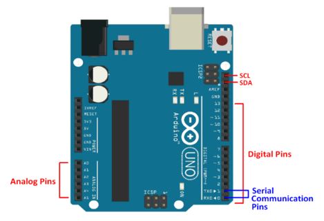
Arduino Uno
With Arduino Uno, you can receive physical information from various sensors and perform various experiments with this information. You can also obtain output from actuators such as motors, LEDs, and buzzers. Basic programming knowledge is sufficient to control such electronic components by connecting them to the Arduino Uno board. The level of electronic and programming knowledge required will increase according to the level of projects. Although there are much smaller and much larger models in terms of size, the size of Arduino Uno is the most standard one for projects. Having 14 digital output pins means that 14 different digital sensors and actuators can be controlled. This is a sufficient number for many projects. 5 of these digital outputs are PWM outputs. Actuators that need to be controlled analogically, such as motor speeds and brightness levels of LEDs, are controlled by connecting them to these PWM pins. The 6 analog inputs on Arduino Uno are for sensors that can receive analog input signals.
With Arduino Uno, you can create everything from the most basic applications like turning LEDs on and off to more advanced projects like drones, robots, smart home automation, burglar alarm systems, and parking sensors. This is entirely related to what you want to do. In short, Arduino Uno is a standard-sized control board that allows you to control electronic circuits in many applications from simple to complex.
In this project, when we read the card whose ID we have specified, the green LED will light up, while when we scan a different card, the red LED will light up.
- Required materials:
- Arduino UNO
- Led x2
- 220Ω Resistor x2
- RFID-RC522 Module
- Breadboard
- Jumper Cable
First, I needed to design the correct circuit diagram. The fritzing schematic of the circuit is as follows:
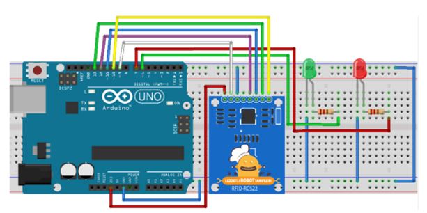
I carefully built the circuit for which I prepared the Fritzing schematic. Then I wrote the code snippet I would use in the Arduino program.
#include <SPI.h>
#include <MFRC522.h>

MFRC522 mfrc522(10, 9);

void setup()
{
Serial.begin(9600);
SPI.begin();
mfrc522.PCD_Init();
pinMode(8, OUTPUT);
pinMode(7, OUTPUT);
}
void loop()
{

if ( ! mfrc522.PICC_IsNewCardPresent()){
return;
}

if ( ! mfrc522.PICC_ReadCardSerial()) {
return;
}

Serial.print("Tag:");
String content= "";
for (byte i = 0; i < mfrc522.uid.size; i++) {
Serial.print(mfrc522.uid.uidByte[i] < 0x10 ? " 0" : " ");
Serial.print(mfrc522.uid.uidByte[i], HEX);
content.concat(String(mfrc522.uid.uidByte[i] < 0x10 ? " 0" : " "));
content.concat(String(mfrc522.uid.uidByte[i], HEX));
}
content.toUpperCase();
content = content.substring(1);
if(content == "A6 4A 76 AC"){
digitalWrite(8, HIGH);
delay(3000);
digitalWrite(8, LOW);
}else{
digitalWrite(7, HIGH);
delay(3000);
digitalWrite(7, LOW);
}
Serial.println();
}
The MFRC522 library I would use in the project was not installed in my program. For this, I downloaded the zip file of the MFRC522 library and added it to the libraries folder inside the Arduino installation directory on my computer.

After adding the library, I compiled and ran the program. Everything proceeded smoothly. After running the project, I first opened the serial port screen and obtained the information inside the card I scanned, then wrote the information I read into the following line.
if(content == "4B 00 B3 22")After introducing the information of the desired card to the project, I recompiled and uploaded the project and scanned my card again. When I showed the card I had introduced, the green LED lit up, while when I scanned a different card, the red LED lit up.
